
A Comprehensive Analysis of Hydrostatic Testing for High-Efficiency Heat Exchanger Tubes (Corrugated Tubes): A “Pressure Test” Ensuring Industrial Safety
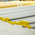
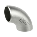
In industries such as petrochemicals, power generation, and refrigeration, high-efficiency heat exchangers are core equipment for energy transfer. Corrugated tubes, as a key component, achieve higher heat transfer efficiency and stronger fatigue resistance thanks to their unique corrugated structure. However, these non-standard, irregularly shaped tubes must undergo rigorous hydrostatic testing after manufacturing to ensure their safety and reliability under high-pressure conditions. This article will provide an in-depth analysis of the entire process of hydrostatic testing for corrugated tubes, from technical principles and testing procedures to industry significance.
I. Structural Characteristics and Testing Necessity of Corrugated Tubes
The corrugated design of the inner and outer walls of corrugated tubes increases the heat exchange area and enhances the turbulence effect of the fluid. However, their pressure-bearing capacity faces greater challenges due to their complex structure. The core objectives of hydrostatic testing are:
To verify the strength limit: Under test pressure exceeding the working pressure (typically 1.5–2.5 times the design pressure), to detect any weak points or manufacturing defects in the pipe body;
To verify sealing performance: To ensure no leakage at pipe end joints, welds, and other connections under high pressure;
To simulate operating conditions: Through static pressure holding tests, to observe the deformation and stress distribution of the pipe body under continuous high pressure, preventing sudden failures during operation.
II. Standardized Procedure for Hydrostatic Testing
According to GB/T 151-2014 Heat Exchangers and ASME VIII-1 standards, the hydrostatic testing of corrugated pipes must follow strict procedures:
Pre-test Preparation
* Visual Inspection: Scan the pipe surface with a 5x magnifying glass to eliminate cracks, pinholes, weld defects, etc.
* Cleaning: Remove oil and iron filings from the inside of the pipe to avoid impurities affecting the seal or causing stress concentration;
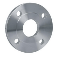
* Sealing and Plugging: Seal the pipe ends with a dedicated test plug or blind flange, and ensure a tight seal with O-rings or metal gaskets;
* Pressure Equipment Calibration: Verify the accuracy of the pressure gauge and test pump to ensure that the pressure reading error is ≤1%.
Test Process Control
Pre-pressurization Stage: Slowly increase the pressure to 50% of the test pressure at a rate of 0.5 MPa/min for preliminary pressure stabilization check;
Formal Test: Continue increasing the pressure to the specified test pressure (e.g., if the design pressure is 2.0 MPa, the test pressure is usually 3.0 MPa), hold the pressure for 10-30 minutes, and inspect the pipe body, welds, and sealing points section by section during this period;
Depressurization Observation: Slowly depressurize to zero, and conduct a comprehensive inspection again for any residual deformation or leakage.
Pass/Fail Criteria
No visible leakage or abnormal deformation under the test pressure;
After depressurization, re-measure the straightness of the pipe body; the allowable deviation is ≤0.3% of the pipe length;
The results of non-destructive testing of welds (e.g., PT dye penetrant test) must meet the Class I weld standard.
III. Risk Control and Technological Innovation in Testing
Although the hydrostatic test seems routine, it harbors hidden risks: the high-pressure water hammer effect may cause pipe end rupture, and inferior sealing rings may fail under high pressure. Therefore, modern testing often employs the following optimized technologies:
Intelligent monitoring system: Real-time data acquisition via pressure sensors, combined with AI algorithms to predict potential leak points;
Acoustic emission detection: Capturing high-frequency acoustic signals during the pressure holding stage to accurately locate micro-cracks;
Digital testing platform: Integrating pressure-time curve analysis, automatically generating test reports and tracing production batches.
IV. Industry Practices and Typical Cases
Taking a corrugated pipe used in a petrochemical plant as an example, its design pressure is 4.0 MPa, and the hydrostatic test pressure reaches 6.4 MPa. During the test, the temperature distribution of the pipe body was monitored using an infrared thermal imager, revealing an abnormally high temperature in the local corrugated area. After investigation, this was confirmed to be a structural defect in the weld heat-affected zone, allowing for timely rework and preventing safety accidents during equipment operation. Such cases demonstrate that hydrostatic testing is not only a compliance requirement but also a “data goldmine” for process optimization.
V. Future Trends: Green Testing and Intelligent Diagnosis
With the advancement of “dual carbon” goals, hydrostatic testing is also evolving towards greener and more intelligent approaches:
Environmentally friendly media replacement: Some companies are experimenting with using biodegradable hydraulic oil to replace traditional water media, reducing wastewater treatment costs;
Digital twin simulation: Predicting stress distribution under test pressure through finite element analysis to optimize test plans;
Blockchain traceability: Storing test data on the blockchain to achieve full lifecycle quality traceability from production to operation and maintenance.
The hydrostatic test of corrugated pipes is a “firewall” for industrial safety and a “microscope” for lean process refinement. Every successful pressure holding test is a rigorous verification of the entire chain of design, manufacturing, and testing. In the era of Industry 4.0, this seemingly traditional test is deeply integrated with new technologies, continuously safeguarding the safe operation of high-efficiency heat exchangers.